The CL2500-MCA 5-channel amplifier is one of the most powerful home audio amplifiers. For sale between 1999 and 2001, it had a short retail life and few were sold until California Audio Labs ceased operations. There are no parts, schematics or service manuals.
CL2500 MCA Power Supplies
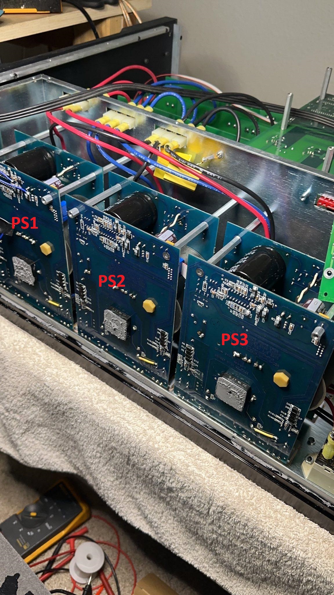
Under the hood, you’ll find a low voltage / standby power supply and three 1500 watt ZVS (zero voltage switching) resonant phase shift switching power supplies providing 4500 watts of continuous power. This is a state of the art power supply design (most patents are from the 90’s) and I’ve never seen them in consumer audio gear. So far, I’ve only seen these types of power supplies recently in modern solar MPPT and EV charging systems. They are extremely efficient at very high power levels and are the “black magic” of state-of-the-art power supply design. To top things off, each amplifer channel uses 20 matched power transistors in their output stages. That’s 100 matched output stage transistors in total.
The unit on my bench has a few problems. Sometimes it won’t power on at all (unable to build rail voltage), while other times it powers on and works fine for hours or days, until rail voltage becomes unstable and starts “motorboating”. The unit does not go into protection and hammers on the speakers until power is removed. This is a loud, startling noise. It usually happens on channels 1 and 2 (power supply #1), but occasionally it will spread to other channels if power is left on.
CL2500 MCA New Soft Start Resistors
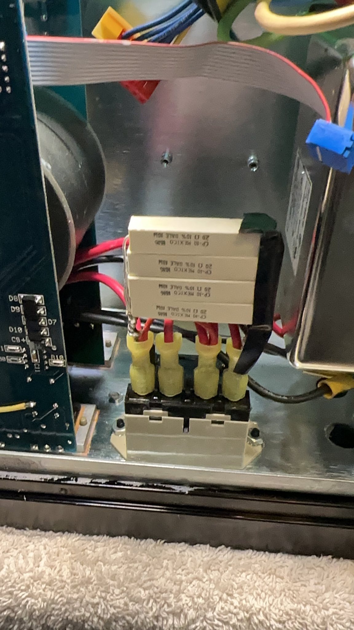
My first task on the bench was to investigate the soft-start system, because it was blowing my 15A breaker every time I plugged the unit in. Moving it to a 20A circuit stopped the breaker popping, but a 50 watt 4-ohm soft-start resistor was open. I replaced it with 4x 20 ohm 20 watt resistors in parallel which resolved this problem.
Next, I investigated the power supplies because when the “motorboating” is happening, rail voltages swing from 30-100 volts a couple times per second. Given the track record of 90’s electrolytics, I ordered new Nichicon electrolytic capacitors – 12x 2200uF, 200v bulk caps and various other smaller values. I re-capped and reflowed solder on all three supplies (8x PCB’s for the power supplies). This was a huge undertaking with a hundred+ screws and everything sandwiched and hard wired together. Testing on the bench seemed fine with channels 1/2 driven to full power for several hours, so I reassembled and returned it to service.
Incorrect Voltage to Control Circuits
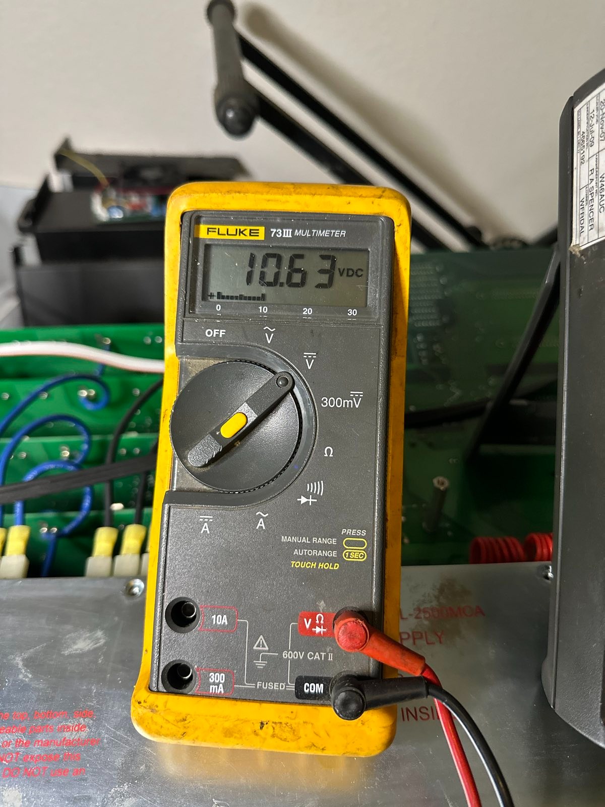
A week later it is back to the bench with the same issue. It’s unlikely that all three power supplies are failing in the exact same way, so I looked for a common point. I probed two 12 volt rails on each switching supply and measured only 10.6 volts. I got the exact same reading for all three units (6 rails total).
According to the switching control IC (UC3879N) datasheet, AT LEAST 12 volts are required for operation. Anything lower should cause a shutdown. The voltage was slowly dropping the longer it was powered on. Once it drops closer to 10 volts, the rail voltages become unstable as the supplies cycle on and off rapidly.
Manufacturing Error
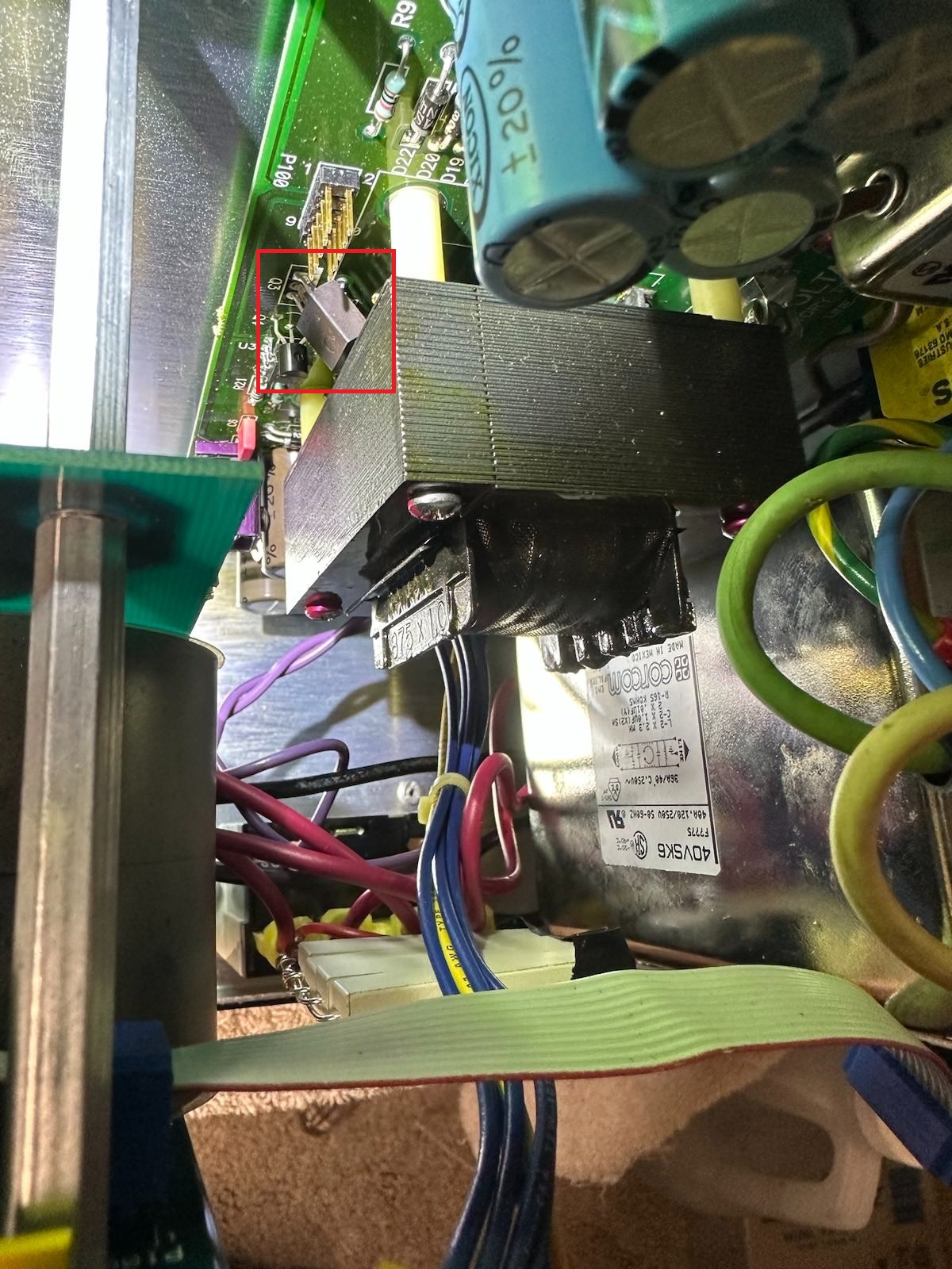
This takes me to the low level power supply board, which provides 12 volts to the switching supplies. On visual inspection, I found an obvious defect – power transistor (Q3) wedged under a transformer, with exposed tab (collector) possibly shorting out on a transformer tap. This transistor is responsible for providing 12 volts to the switching supplies. It is jammed in such a way that it could not be removed without cutting the transistor legs or desoldering the transformer. I chose to cut the transistor off, desolder the legs and install an identical unit (TIP32C) in the correct orientation.
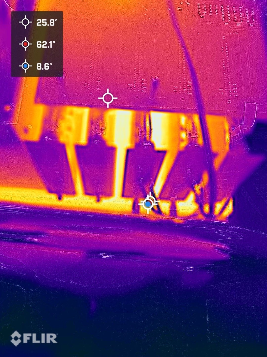 The unit is back in proper working order. I am considering adding active cooling fans at some point, because this passively cooled amplifier runs very hot with an idle draw of almost 500 watts. I also plan to interface with the RS232 control port using an Arduino to turn the amplifier on and off remotely.
Comments are closed.